In this Section, two examples are used to illustrate a number of features of the GA that make it potentially attractive to the control engineer. The first example of the optimization of the parameters of a control system shows that GAs can be used to search a parameter range to satisfy a number of competing design criteria. The second example shows the use of GAs in dynamic optimization.
Lateral control of an autonomous road vehicle [11] is presented. The lateral control is based on a linearized, time varying model of the vehicle's response to steering inputs. The controller is implemented as a continuous transfer function. Non-linear conflicting requirements of safety and comfort have to be satisfied by the controller. The performance of the control system is measured by a complex cost/objective function, combining the multiple objectives into one function using the weighted sum method.
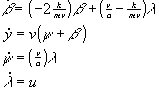
A simplified model of lateral control on a straight road ([11]) is:
with state variables: ß: sideslip angle, y: offset from the lane center, w: difference between yaw angle of the vehicle and course angle of the road and lambda: steer angle; control input: u: control action; variable and constant plant parameters: v: velocity, speed (20 m/s), m: vehicle mass (5800 kg), a: wheel base (4.25 m)and k: lateral friction coefficient (150 kN/rad).
The primary control objective is to keep the car at the lane center. Furthermore, it is required that
The conflict between the first and the third requirement and the nonlineartity of the last requirement constitute the main difficulties of the lateral control problem.
The controllers were implemented as Simulink models. As all the parameters of the models are global and thus changeable, here no numbers for a system are given. All these calculations are performed inside the objective function.
The Simulink model for the system is shown in figure 1.
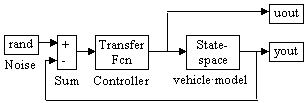
Fig. 1: Simulink model of the system
For the continuous system the model in equation 1 was directly used for the simulation. Preceding the simulation a stability test was performed. Thus, the state space system was converted to a transfer function. Then the system was combined with the controller and the stability test of the closed loop system could be performed. If the system is stable (the real part of all roots of the denominator polynomial are less then 0), the simulation is carried out. Otherwise, an arbitrarily high objective value is assigned for this structure, see equation 4.
The control objective function has to maintain the following requirements:
To take account of all these requirements the following objective function can be constructed:
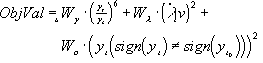
The first term combines the first two requirements: minimizing large offsets quickly and tolerating small offsets at the same time (smaller than yc-border of tolerance for lane offset), using high power. The second term penalizes the lateral jolt (comfort component). The third term is only employed if the sign of the offset of the car during simulation is different than the offset at the begin of the simulation, thus penalizing the car overshoot over the lane center.
The weight of the three objectives is implemented by the weighting values Wy (lane offset), W( (lateral jolt or acceleration) and Wo (lane overshoot). In [9] the following values were used:

When the system is unstable (see stability test above) a very high objective value is assigned to this system. In order to provide a difference in the objective values of unstable systems the worst root is used. Thus, the objective function provides hints for the search direction and a ranking is possible. If the same value were assigned to all unstable structures the search would be random.

To force the system back to the lane center during the simulation, a fourth term can be added to the objective function. This term penalizes all lane offsets after a specified time. For example, if the simulation runs over 10 seconds, all lane offsets between 4 and 10 seconds are highly penalized. Thus, at the beginning of the simulation the above objective function is used. Later, a strict minimization of the lane offset is enforced.
The genetic algorithm was employed with the objective function of equation 2 and the system model equation 1. All the standard parameters of the model were used including a speed of 20 m/s. Figure 2 shows the evolution of the objective value for the best set of controller parameters found during an optimization.
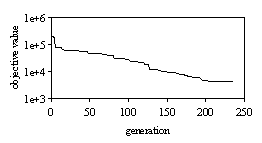
Fig. 2: Evolution of objective value for continuous system
The first stable structure is found during the first generations. At the end of the simulation a very good parameter set is found, see equation 5.
The controller parameter set of the continuous controller is:
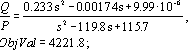
Figure 3 shows the control action obtained using the controller in equation 5. The lateral offset of the system over the optimized period is shown in figure 4.
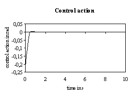
Fig. 3: Control action for controller parameters of equation 5
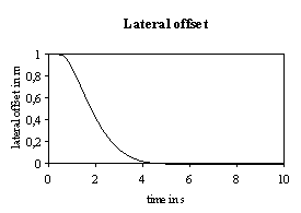
Fig. 4: Resulting lateral offset for controller parameters of equation 5
Dynamic optimization problems are complex and difficult to solve. The use of dynamic-optimization specific methods, such as the Hamiltonian, is complicated and problematic. The application of specific methods requires a large amount of mathematical support even for systems of moderate size, and only the most trivial systems can be solved analytically.
In the following example, each individual in the genetic algorithm corresponds to a (discrete) control vector. Each variable in an individual is associated with the control input at a time step of the dynamic optimization problem. In this section, x is the state vector and u the control vector of a system.
The double integrator (push-cart system: straight movement of a body under the influence of a force) should be optimal with respect to control energy as it moves from one state to another. The control vector, u, is the force acting on the body, the state vectors are speed, x1, and position, x2. The double integrator problem is described by the following state equations.

The value of x2 has to be changed during a time period with as little control effort as possible and the final conditions/constraints must be met, such that the following criteria are satisfied.
Equation 7:

The objective function to be minimized is:
For these conditions an analytical solution is found to be:

Figure 5 shows the optimal control vector and states for the continuous system:
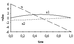
Fig. 5: Input and states of double integrator for optimal solution
To enforce the end conditions/constraints we used a penalty function. Thus, the multiobjective problem was transformed into a singleobjective problem.
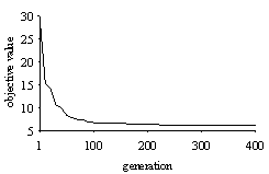
Fig. 6: Objective value of best individual per generation for the optimization of the double integrator
Figure 6 shows a typical graph for the optimization of the double integrator using the Multi Population Genetic Algorithm (part of the GA Toolbox) with default parameters. The control result is identical to figure 5.
Though the examples are relatively simple they provide a starting point for understanding the use of the GA Toolbox in the area of control systems. For further evaluation of genetic algorithms the GA Toolbox incorporates a number of specific control examples. We are currently applying the GA Toolbox to more advanced examples and applications.